
European solar installers are no strangers to ungrounded PV systems, but in the United States, where traditional grounded systems are the norm, ungrounded arrays are not commonly used. Thanks to revisions in the National Electrical Code (NEC), the U.S. deployment of ungrounded PV systems -- which are safer, simpler and faster to install, and more cost-effective than grounded systems in many cases -- can be accelerated.
To satisfy NEC 690.35 requirements for ungrounded photovoltaic power systems, such systems must be able to operate with ungrounded PV source and output circuits that are properly equipped with the appropriate disconnects, overcurrent protection components, and ground-fault protection devices. The ground-fault system should be capable of detecting a fault, indicating that a fault has taken place, and be able to automatically disconnect all conductors or cause the inverter or charge controller connected to the faulted circuit to automatically cease supplying power to the output circuits. Finally, a properly designed and installed ungrounded PV system must include source conductors consisting of nonmetallic jacketed multiconductor cables, conductors installed in raceways, or conductors otherwise listed as PV wire installed as single conductors.
There are two types of grounding in a PV installation. The grounding electrode conductor (GEC) connects the current-carrying circuit to ground and includes the negative or positive of a DC array, the neutral of a split single-phase AC system, or the neutral of a bipolar DC system. The other type is the equipment grounding conductor (EGC), which connects exposed, possibly energized conductive surfaces such as module framing, racking, aluminum enclosures, and other noncurrent-carrying metal parts to ground.
Historically, most manufacturers produced inverters for the U.S. with a system ground in which the positive or negative conductor from the PV module was intentionally bonded to ground inside the inverter or combiner box. A new NEC-compliant family of microinverters, which incorporate “integrated ground” technology, have neither the positive or negative module conductor connected to the chassis and thus facilitate the design and installation of ungrounded PV systems. The microinverters need no GEC interconnections since the unit physically isolates the DC circuit within the microinverter from ground. The EGC for the microinverters is integrated into the interior wiring of the AC cable system, which led to the designation of this configuration as an “integrated ground.”

Some installers and electrical code enforcers might misinterpret the use of the term in reference to these microinverters, thinking that there is a system ground that is somehow incorporated into the inverter itself. This is not the case. "Integrated ground" in this instance refers to the design element that fully integrates the equipment ground for the metal case into the AC cable system.
By integrating the equipment-grounding conductor into the AC cabling, the microinverter system does not require additional copper grounding wire, resulting in a reduced bill of materials, less field labor during installation, and the elimination of potential arc fault events. Once an installer hooks up the microinverter’s AC connector to the AC cable and attaches the DC connectors to the PV module, the task is completed.
The ungrounded microinverter also has the ability to closely observe the isolation of the ungrounded DC circuits. An advanced onboard insulation monitoring system is used to detect ground-faults, enabling a significantly more sensitive isolation monitor by several orders of magnitude compared to detectors for grounded systems. In this way, ungrounded systems are actually safer than grounded systems since they can detect a variety of ground faults at significantly lower current levels.
If the PV module and support structure are properly bonded to each microinverter, sufficient equipment grounding can also be provided, leading to smoother system installation. Once listed bonding devices or bonding jumpers are used to bond the PV module to its support structure, and listed bonding devices or bonding jumpers are used to bond the support structure to the microinverter, no external EGC is required since the equipment ground has already been supplied in the AC output cable harness.
Some jurisdictions have taken issue with the use of certain grounding and bonding devices in conjunction with PV modules or mounting structures. If no bonding devices are approved by the authorities having jurisdiction (AHJs), the methods approved by the AHJs can still be implemented for the PV modules and mounting structure. However, the AHJ should not require any additional bonding of the case of the integrated ground-equipped microinverters since the listing of the inverter and the AC output cable clearly address the bonding of the exposed conductive surfaces of the devices.
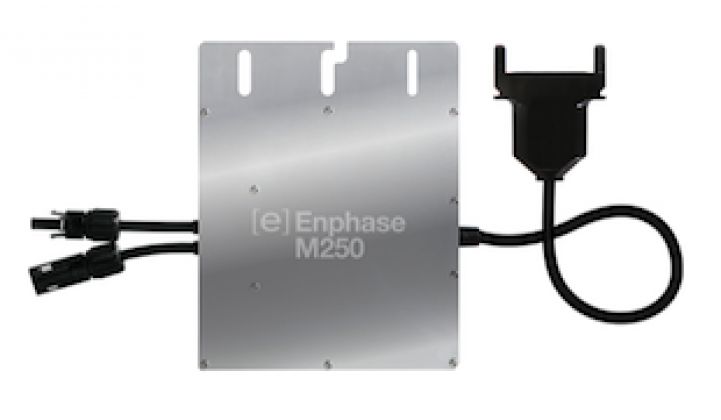
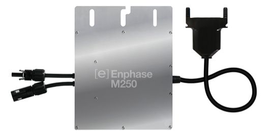
The appearance and configuration of integrated ground-equipped microinverters differ from previous generations. There is no grounding terminal at the top of the device, which also features a flat front lid (there is no longer a groove for a copper grounding wire), thus making it simpler for installers, inspectors, and AHJs to identify microinverters incorporating the technology.
Since the deployment of an integrated ground microinverter system requires certain modifications of standard installation and inspection methods, it is essential to provide educational and instructional materials during the transition. System designers and installers, AHJs, code compliance professionals, and other interested parties can access both a technical brief and an informative white paper on microinverters and ungrounded PV arrays. The latter document explains solar grounding terminology and provides examples of common PV array building methods that follow the NEC-compliant grounding procedures required in the installation of the Enphase M215 and M250 microinverters.
The publications and a brief instructional video are available on a dedicated landing page for microinverter grounding information: http://www.enphase.com/Grounding. A lengthier instructional video can be found below.


 41
41
 15
15
 9
9