As any PV system designer knows, small changes in layout parameters for commercial projects can have a sizable effect on energy production. If you reduce spacing between module rows, you can add more modules to a given roof space. If you raise the module tilt angle, you can increase production. In both cases, just watch out for shading cast from one module row onto another.
There are many examples where a little extra knowledge about commercial design goes a long way toward reducing installation costs and improving return on investment. This article identifies four of them. But the key is not only recognizing how to optimize design. It’s important to use robust software that provides extensive control and lets users instantly see the results of the design choices they make.
Here’s why. If your design process is riddled with time-consuming tasks, like manually drawing array layouts and entering data into spreadsheets, there’s a hidden penalty that discourages you from creating multiple versions of the design and comparing results. Without comparing versions of the design, you’ll never know if a slight adjustment in layout parameters would yield better value. It’s like signing a solar installation contract without comparing bids.
Modeling rooftop shade
If you’re not familiar with PV design, you might be surprised to learn that there is more than one way to model shade patterns caused by rooftop obstructions. Thirteen years ago when PVComplete co-founder Daniel Sherwood started in the industry at PowerLight Corp. (then one of the world’s largest PV system integrators), he was taught to use a triangular-shaped pattern called "shade pie." The rule of thumb was to keep modules out of the shade for at least a couple hours on the shortest day of the year.
You can get a more accurate production estimate by using a different shade pattern resembling a butterfly wing, with wide shadows in the morning and late afternoon but very little shadow at all when the sun is at high noon. This is based on keeping modules out of the shade on a more typical solar day, generally at the equinox.
Designing with shade pie allows you to fit more modules on the roof because it creates less shade. Plus, the optics are good. If you look at the roof in the middle of the day at any time of year, no modules will be shaded.
The butterfly is more realistic if you really want to minimize shading loses, because the roof space covered by the wing will be shaded during sunny months of the year when production is high and you really don't want to shade the modules.
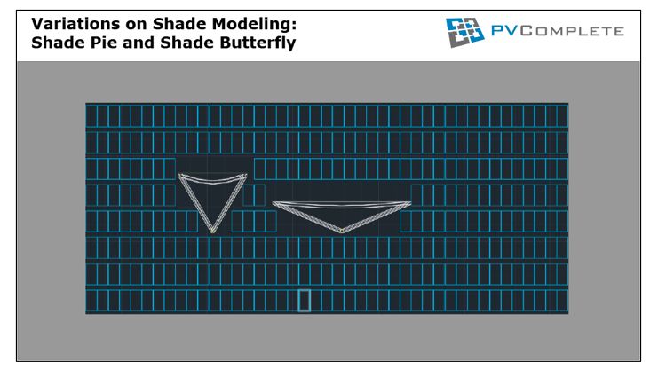
Shade pie (left) and shade butterfly (right)
Leapfrog module wiring
Most solar modules have lead wires extending over 3 feet from the junction box. The wire length makes it possible to connect modules in landscape orientation. But when systems are configured with a portrait orientation, as they often are, the installation crew has to take on extra work to fix the excess wiring in place. That’s one step in the installation process creating waste by increasing material costs and labor costs.
If you’re certain that the lead wires of your modules are long enough, you can use the excess material to your advantage by connecting every other module in series instead of creating a daisy chain from one module to the next. By leapfrogging modules, you eliminate the time needed for wire management.
As an added advantage, leapfrog wiring also reduces the length of the home-run connection of positive and negative wiring. When daisy-chaining modules, the home-run connection runs the length of the row. When leapfrogging modules, the ends of the home-run connection are on the same side of the row.
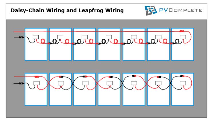
Daisy-chain wiring (top) and leapfrog wiring (bottom)
Optimizing row spacing
Finance plays an important role in determining the design objectives for commercial PV projects. Certain investors seek to derive the most value from systems with the highest capacity. Others attempt to maximize energy production per module. Still others aim for the greatest value in terms of energy output relative to the cost of equipment.
If you want the greatest energy production per module, it makes sense to space out the rows as much as necessary. If you want to build the biggest system without regard for output, you go to the opposite extreme and reduce inter-row spacing. As you increase system density, packing module rows tighter and raising the module tilt angle, energy output goes up until you reach an optimal point beyond which any further density will cause self-shading and output starts to decline.
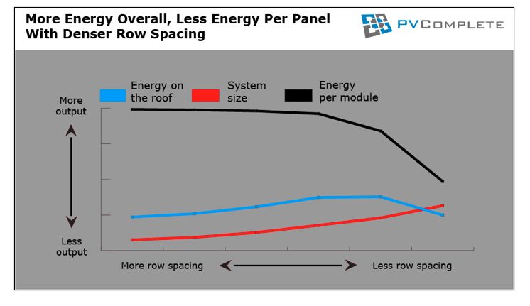
Pushing rows close together gets you more modules on the roof, but it makes each module a little less productive. Maximizing energy per module gets you the most bang for your buck.
Mitigating voltage drop
PV designers have two good reasons to minimize voltage drop: to avoid wasting energy and to ensure that inverters always work according to electrical specifications. In project bidding, designers are often asked to keep voltage drop below 2 percent on DC input circuits, 2 percent on AC output circuits and 3 percent overall. These values are not mandated by code, but they do generally indicate whether a system is designed to operate in a reasonably efficient manner.
One simple way to reduce voltage drop is to use current-carrying conductors that are larger than necessary for the project. A larger conductor decreases electrical resistance, thereby reducing voltage drop on the line. Reducing conductor length would have the same effect, but options for the designer to do so are limited based on the placement of equipment and the grid interconnection point. It’s important to consider the cost of using larger conductors; depending on the system design, it can be less expensive to install a larger system than to use larger conductors.
Another piece of conventional wisdom is that to minimize voltage drops, systems are better off with long runs of DC wiring than long runs of AC wiring. This is not always the case. Again, it’s important to consider the system design, particularly the voltage of the DC and AC wiring. If the array has a 1,000-volt DC nominal rating and the inverter feeds into the grid at 240 volt AC, then certainly it's better to have a long DC run. If you have a 600-volt DC system and a 480-volt AC tie-in, you are better off with long AC runs and short DC runs.
***
Claudia Eyzaguirre and Daniel Sherwood are co-founders of PVComplete, a solar design platform that generates fast and accurate project design both on the web and in a seamlessly integrated AutoCAD environment.


 41
41
 15
15
 9
9